

Author: Shenye Plastic TechnologyDate:2026-06-30Pageviews:136
In the world of high-volume manufacturing, a plastic injection mold is often referred to as a "masterpiece of engineering." It is not merely a block of steel with a hole in it; rather, it is a highly sophisticated assembly of synchronized systems designed to produce thousands, or even millions, of identical parts with micron-level precision.
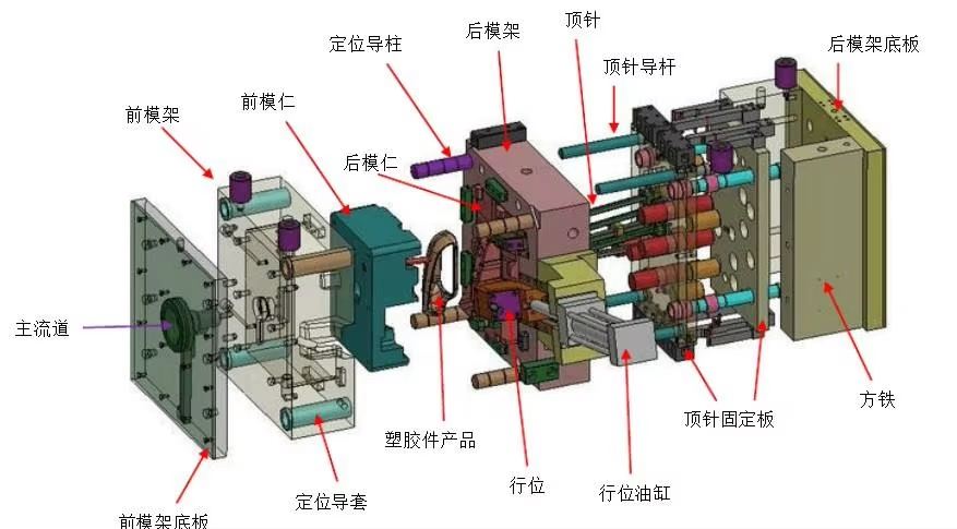
For OEMs and product developers, understanding the overall structure of a mold is essential for optimizing costs and ensuring part quality. Here is a technical breakdown of how a plastic mold is structured.
The mold base is the structural frame that holds all other components together. Think of it as the chassis of a car. Most manufacturers use standard mold bases (such as DME or HASCO standards) consisting of several steel plates:
Fixed Plate (A-Plate): Attached to the stationary side of the injection machine.
Moving Plate (B-Plate): Attached to the moving side of the machine, which opens and closes during each cycle.
Support Plates: These provide the necessary rigidity to withstand the immense pressure of the injected molten plastic.
This is where the magic happens. The structure is divided into two main halves:
The Cavity (Female side): Usually located in the fixed half, it defines the external shape and "show face" of the part.
The Core (Male side): Located in the moving half, it forms the internal geometry and ribs of the part. When the mold closes, the space between the cavity and the core—known as the parting line—creates the exact volume of the final product.
Since the mold opens and closes thousands of times, the cavity and core must align perfectly every single time.
Guide Pins and Bushings: These are high-precision steel rods and sleeves that ensure the two halves of the mold meet without even a fraction of a millimeter of misalignment. Any wear here leads to "flash" or part defects.
This system is the "plumbing" of the mold. It channels the molten plastic from the machine nozzle into the cavities.
Sprue: The main entry point.
Runners: The tunnels that distribute plastic to different parts of the mold.
Gates: The narrow entry point into the actual part (as discussed in our previous technical guide).
Cooling typically accounts for 60% to 80% of the total cycle time. Efficient structure design must include:
Cooling Channels: A network of bored holes inside the plates through which water or oil circulates.
Baffles and Bubblers: Specialized inserts used to reach deep cores or areas that are difficult to cool, ensuring the part solidifies uniformly to prevent warping.
Once the part has cooled and solidified, it must be removed from the core.
Ejector Pins: These are rods that push the part off the core as the mold opens.
Ejector Plate: The mechanism that moves all pins simultaneously.
Return Pins: These ensure the ejection system retracts fully before the mold closes for the next cycle.
At Sunye Plastic, the overall structure of each mold is meticulously planned using advanced Moldflow Analysis and CAD software. By optimizing the relationship between these six systems, we reduce cycle times, minimize material waste, and extend the lifespan of the tooling.
Whether you are developing 3C digital electronic components or complex automotive shells, a robust mold structure is the primary insurance policy for your project's success.
Previous:How to solve the cracking problem of drawn parts in injection molds?
Next:没有了!

QR code attention
Shenye plastic


